Man, it’s been a while since I posted on here, huh? Well, all I can do is apologise. It’s been a crazy few months here.
I’ve been to the BETT show in London to interview Dobot about their new 3D printer, I’ve made a couple of trips to Scotland to visit friends, and I just spent 5 days in Birmingham interviewing people at The Photography Show and to meet up with some old and new friends. I’m also moving house in the next couple of weeks, and there’s been a lot of prep work for that.
In between that, though, I’ve been getting into 3D printing.
No, I haven’t just been printing off models of Benchy, Bender and Groot. I wanted to do something that would actually be useful. Something that would help me with something related to photography or shooting video.
So, with this in mind, I decided to have a go at motorising one of my camera sliders. The slider itself is nothing special. It was just something I found cheap on eBay to play with.
It’s a slight variance on this design and it works quite well manually, considering there’s no flywheel. But I wanted something I could automate. I wanted to be able to film stuff and have it bounce back and forth at different speeds continuously, say as the wide shot for an interview. And I wanted to be able to slow it right down for timelapse, too, which can’t be done by hand.
I’m not using the new Dobot Mooz 3D printer mentioned above to print the parts, but I am using the Dobot Magician. The Magician is not actually a dedicated 3D printer, but a robot arm that happens to have a 3D printing head.

After a little playing around to tweak the settings, the Magician is turning out to be quite good as a 3D printer. It can’t replace a real 3D printer, as there’s no heated bed, and the inherent nature of robot arms means that certain things aren’t quite as reliable as a printer with separate true linear X, Y and Z axis motors. For this task, though, it’s good enough for now.
The lack of heated bed means that I can only really print PLA. And there’s no part cooling fan. So, there’s a little curling. The filament is sticking to the tape just fine. Extremely well, in fact. So well, that it’s actually lifting the tape off the glass as it curls up.
Again, though, for this task, it’s good enough, and a little curling on some non-vital surfaces won’t matter. It’s flat where it counts, which is where components connect to the slider itself.
So, what’s the first job?
The first thing to do was to figure out what exactly I needed to design and what components already existed, as well as which of those components I could print and what I had to buy.
So, the first list is the 3D printed parts. The GT2 stuff already existed on Thingiverse, but the brackets and connectors I had to design from scratch to fit my slider.
- An end bracket to hold the idler pulley
- A bracket for the other end to attach a motor
- Connectors to attach a belt to the carriage
- One GT2 motor pulley
- One GT2 idler pulley
- Some GT2 belt clips
Pretty much everything else has to be bought.
Right now, I’m not concerning myself with the electronics side of this. I have a stepper motor driver (these usually come in packs of 5 for building 3D printers) and an Arduino for developing. But I still need to figure out how I want to actually have it take input from the user to control it.
I’m going back and forth between simple switches and knobs, an ASUS Tinker Board with 7″ touchscreen LCD with complete custom UI, or do I just give the Arduino Bluetooth capability and make an app for my phone?
For now, though, I’m just toying with ideas on that side of things, based on how difficult I want to make my life. Once the mechanical side is done, then I’ll worry about the electronics and interface.
What 3D software?
I used to do a lot of 3D stuff with Maya in a former life. Then I stopped using it when I made the switch to photography & video because I simply didn’t really need 3D tools anymore. Since getting back into 3D, I’ve been using Blender. These days, I’m only doing 3D stuff as a hobbyist, so I don’t want to spend thousands on software.
For this, though, I felt that Blender just couldn’t cut it for what I needed. Or, to be more precise, I didn’t want to have to put in the time it would take to get things perfect with Blender. There’s no easy measurement system in Blender for designing technical parts. So, it would’ve been a lot of 3D printing trial and error, testing if parts fit, making adjustments, trying again and wasting a lot of filament.

A few people had suggested I check out Fusion 360, so I did. I had no idea what I was doing with it, but I found a perfect beginner series on YouTube by Lars Christensen.
It doesn’t cover everything of which Fusion 360 is capable, but it was more than enough for my current modest needs. Coming from Blender, it’s not super intuitive, but, once you know the basics, it’s amazing how easily you can work through it.
Modelling
The first job was modelling the end cap for my slider. There were no plans, designs or schematics online, so I had to measure everything myself, sketch it out, then extrude and add screw threads to get things just right.

My first design wasn’t perfect. I thought something looked a little off on-screen, but it wasn’t until I 3D printed it that I realised where I’d mismeasured. So, back into Fusion, some double checking of measurements, a bit of tweaking, reprinting, and my slider end plate model was spot on.
I didn’t need to really print this end plate for any purpose other than to check that the measurements matched up to the real world metal end plate on my slider. After this, it was purely for reference for the two brackets I needed to make.
The first of those holds the bearing & GT2 idler pulley. This end spins freely. It’s a simple design, and the only other real-world measurement I had to make was the inner diameter of the bearing for the column that sticks up to mount it on.

This piece came out perfect on the very first print, as it was modelled around the end plate I’d previously created. So it connected to the real metal plate on the end of my slider with very little wiggle.
Next up was the bracket at the other end to which the motor will mount. I don’t actually have the motor yet. I’ve ordered it, but it won’t be here for another week or so. The schematics for NEMA 17 motors are pretty standard, though, so it was easy to plan ahead.

The motor fits underneath and bolts down from the top with M3 screws and the spindle sticking through the hole. A pulley is attached to the spindle which drives the belt.
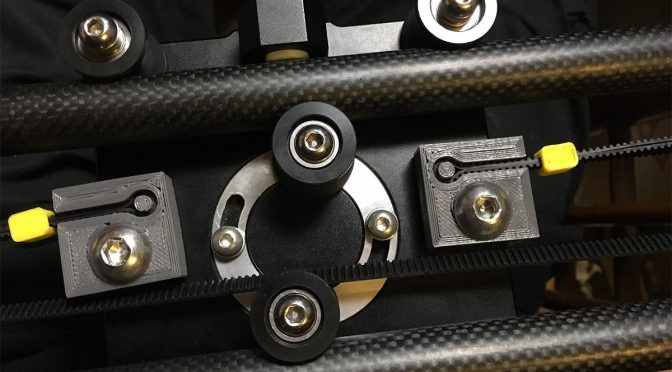
I didn’t model the slider carriage in Fusion 360, but I did need to design up a couple of belt connectors to attach to it. These bolt into the underside of the carriage. They’re designed in such a way that the belt sits in a channel and loops around a column.

The slot in which the belt sits is fairly snug, but it’s loose enough that I can pull it tight to tension it. Once tense, on go the belt clips. I was a little worried about having the channels completely open like that. With enough tension, though, they should be fine.
It’s still possible they could work loose during use, though. So, I may flip the design upside-down, and attach the belts to the connectors before I bolt them on so that they can be sandwiched between the printed plastic below and the metal carriage above. I’ll also need to move the notch that holds it square to the edge of the carriage, too.
As I said, I’m still waiting for my motor, so I can’t fully test it yet. And I’ve not worked with stepper motors on the Arduino before, either, so that’s going to take some learning.
Printing
The printed parts and components I ordered fit together very well with each other so far. Surprisingly well, actually. At least, I was surprised. I thought, for sure, I’d mess something up.


So, even though I don’t have the motor yet, it feels pretty good. The parts fit well, although I don’t have an Allen key to fit the 3/8-16″ bolts – The bolts used to attach the pieces to the ends of the slider and the carriage. So, they’re just finger tight for now.
The designs are a little basic and brutal, but I do plan to reprint these at some point anyway. As they’re PLA, they’re not the most indestructible items in the world. So, eventually, I’ll get a proper 3D printer with a heated bed and redo them in ABS or PETG so they’re a little more durable.
Until then, though, I think this should work for a while. Now I just need that motor to show up.
Once it’s all fully assembled and I’ve figured out how it’s all going to work, I’ll put together a video about the whole process – possibly even a series. So, don’t forget to subscribe to me on YouTube if you haven’t already!
I also plan to have a go at some of these in the future, too. That 4×5 pinhole looks extremely cool, but I’ll need a bigger printer.
As for the Dobot Magician, even after I get a dedicated 3D printer, I still have a few other cool ideas I want to try with that, so stay tuned!